
- News
- Industry Database
- Events
Icelandic Fisheries Exhibition
IceFish Conferences
The largest commercial fishing exhibition in the North. Co-located with the Icelandic Fisheries Exhibition, the IceFish Conferences bring the seafood sector together for three days of insight, innovation and connection. Visit the IceFish Website Visit IceFish Conferences
- Special Reports
By-Product Solutions
Smart, Connected Seafood Processing
Land-Based Aquaculture Technology
Greener Fishing
January-February 2026 March-April 2025 July-August 2025 November-December 2025 
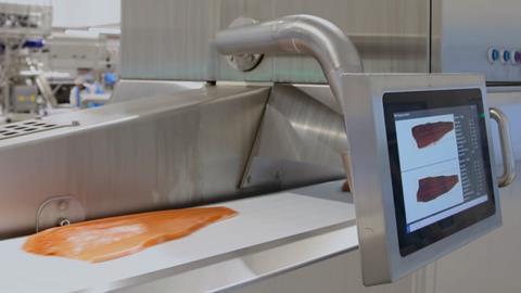
Cutting waste and maximising value Robotics, analytics software and other Industry 4.0 technologies are helping to scale-up productivity New production systems are escalating the industry’s contribution to global food security Fisheries are becoming increasingly responsible and sustainable thanks to new technologies and initiatives Read More Read More Read More Read More
Fuel savings and greater efficiency for new GE engine
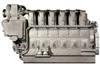
GE Transportation has introduced new V250 12- and 16-cylinder medium-speed diesel engines for marine and stationary applications which are claimed to deliver fuel savings of as much as 6.5% compared to the company’s earlier models, and offer 25% greater power density in the compact designs, while meeting US Environmental Protection ...
Continue this article…
Already subscribed? SIGN IN now
Register for free access to more World Fishing & Aquaculture content
Want to read more? It only takes a minute to sign up for a free account and you’ll get to enjoy:
- Weekly newsletters providing valuable news and information on the commercial fishing and aquaculture sector
- Full access to our news archive
- Live and archived webinars, podcasts and videos
- Articles on innovations and current trends in the commercial fishing industry
- Our extensive archive of data, research and intelligence
Get more free content sign up today
